Wondering how to make a robot arm without buying a kit? Start with hobby servos, an Arduino UNO and a few potentiometers, move each joint directly, and add kinematics only when you need to place the gripper at coordinates.
This arm is one project within the broader subject of how to build a robot, so use that hub for frames, power and other builds. The sections below take the common beginner assumptions in turn and tie each design choice to a part you can buy.
What a first robot arm actually needs
A first robot arm is a small set of servos, one microcontroller and a way to command each joint. One Arduino Project Hub build grabs objects with just three servos and one Arduino UNO. Another beginner project builds a small arm from four servos and drives it from a Raspberry Pi using Python, according to a robotics blog. Arm projects range from simple pick-and-place to complex inverse kinematics arms, so choose the simple end first. The table separates the assumptions that stall most beginners from what the build evidence supports.
| Common assumption | What the builds show | Planning use |
|---|---|---|
| You must buy a commercial arm kit | A forum poster described a $150 kit as more than they could allocate to a one-shot project, while the Arduino project runs on three SG90 micro-servos and one Arduino Uno Rev3. | Price a parts list instead, and treat a kit as optional. |
| Any cheap servo will do | The SG90 is rated at 1.8 kg-cm at 6V. It suits proof-of-concept or educational arms, but cheap servos can lose precision and durability under heavy or prolonged loads. | Keep the SG90 for light, short demonstrations and step up for real payloads. |
| You need inverse kinematics immediately | The Arduino project maps each potentiometer reading (0 to 1023) to a servo angle (0 to 179 degrees) with no kinematics at all. | Get direct joint control working first. |
| You need a 3D printer | The Arduino project assembles its arm with a hot glue gun, and a forum builder without a printer considered a balsa wood chassis. | Choose a fabrication method you can actually access. |
Figures come from the Arduino Project Hub arm build and a DroneBot Workshop forum thread, both of which are maker documentation rather than manufacturer datasheets.
Parts list for the build
The Arduino project’s bill of materials is a sensible template because every line has a clear job. It lists no prices, and costs vary by supplier, so price each line against current listings before ordering.
- Controller: one Arduino Uno Rev3, which reads the knobs and generates the servo signals.
- Actuators: three SG90 micro-servo motors, one for each moving joint.
- Input controls: three rotary potentiometers, one per servo, plus two tactile switches.
- Indicators and passives: five green LEDs and resistors in 1k and 220 ohm values.
- Assembly: a breadboard and a hot glue gun.
The potentiometers and switches are what let the arm be played by hand and have positions saved, which is why they sit in the list alongside the servos. If you plan to move up in strength, budget for the servo upgrade covered next and for the structural material discussed afterwards.
Servos and torque: which actuators suit beginners
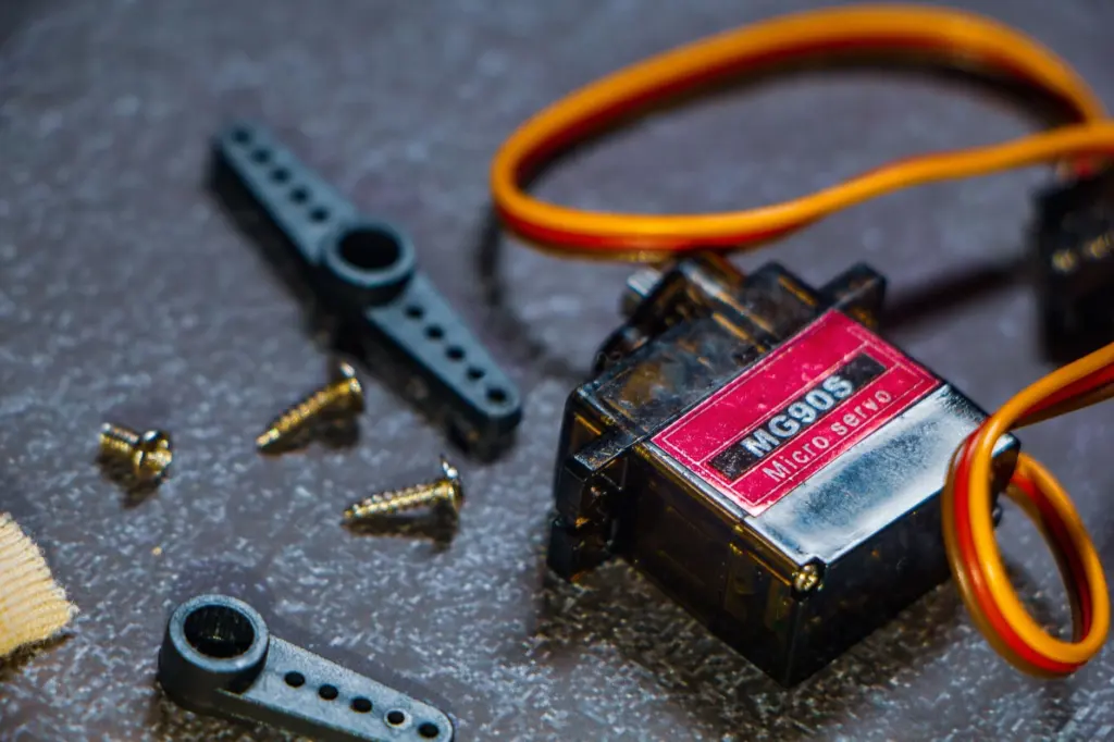
Servos suit beginners because they take a target angle directly and need no separate position-feedback hardware. Both beginner projects above use them. The trade-off is strength. Forum builders note that the SG90 has limited torque, at 1.8 kg-cm at 6V, and that cheap servos can suffer from precision and durability issues under heavy or prolonged loads. The same forum thread says SG90s are fine if the project is primarily proof-of-concept or educational.
Pick by what the arm must do:
- Desk demo or learning project: SG90 servos are adequate and match the proven Arduino build.
- Arm you want to last: the forum suggests MG90S servos, which are metal-gear versions of the SG90.
- Heavier lifting: the same thread points to higher-torque servos such as the MG996R.
Torque is not the only filter, since a stronger servo adds weight at the joints, but start the selection from the load you expect the gripper to hold. With the actuators chosen, the next job is attaching them to something rigid.
Mechanical build: links, horns and materials
Each joint is a servo whose horn screws to the next link, so link material only has to hold the servo and the weight beyond it. Material choice is therefore a question of tools, not theory. One maker blog describes a nearly one-metre-tall arm made from nothing but 3D-printed parts, designed in Fusion 360 and simulated in Python on Google Colab. That is an ambitious route, and it is not required for a first arm.
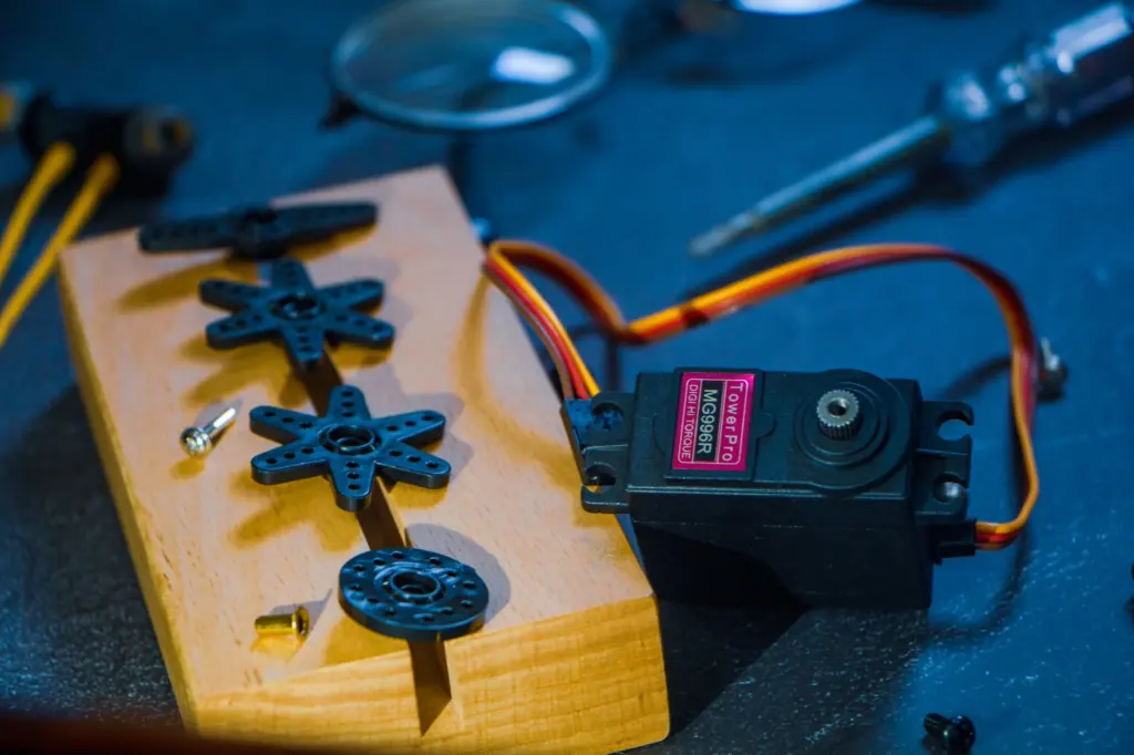
If you have a printer, print brackets and link plates in a CAD package you know. If you do not, the Arduino project shows hot-glued construction is enough for a light arm, and a forum builder without a printer considered balsa wood for a chassis so that custom parts could still be fabricated. Whichever material you pick, the geometry underneath is trigonometry: link angles and positions are computed from the lengths of the arm’s sections, which becomes important when you add coordinate control later.
Wiring and driver electronics
In the simplest arm, each potentiometer feeds one analog input and each servo is signalled from the Arduino. The Arduino project supplies a basic wiring schematic as a downloadable image, which is the best starting diagram for the parts list above. Follow it rather than improvising pin assignments, and add the LEDs and their resistors only after the servos respond.
Beyond the direct-wired layout, a forum builder drove servos from an ESP32 through a PCA9685 servo driver board, following a published tutorial. That is a reasonable next step when you want more servos than the controller handles comfortably. Once the arm moves, wires snag and pull at joints, so plan robot cable management before the build is final. If you later think about adding range sensing to an arm, LiDAR vs Radar: How They Really Differ and Which To Use In 2026 explains how those two technologies differ.
Controlling the joints: direct mapping first, kinematics second
Joint control starts with a single line of mapping. The Arduino project reads each potentiometer with analogRead, which returns 0 to 1023, and maps it to a servo angle of 0 to 179 degrees. Turn a knob and the joint follows. The same code saves 5 positions and replays them with a fixed delay of 1050 ms between moves, which gives you a repeatable pick-and-place routine without any maths. A builder on the forum also uses smoothing code for the servo motors, which softens the jump between targets.
Kinematics comes in when you want to say where the gripper should go rather than what angle each joint should take. RoboDK’s explainer defines inverse kinematics as the mathematical process of calculating the joint positions needed to place the end effector at a target position and orientation. Three points affect a beginner’s plan:
- Multiple answers: forward kinematics has only one solution, while inverse kinematics often has several, so your code must choose between them.
- Solver type: numerical solvers are slower than analytical ones, but they are the only option when the kinematic structure is complex or unusual.
- Home-built arms: an arm made from scratch by connecting motors and links will usually need its own solver.
One forum builder proposed the FABRIK2D Arduino library to replace the potentiometers and automate positioning, which is a practical way to avoid deriving the equations yourself. Take the stepwise route: hand control, then recorded positions, then coordinate control.
Testing and tuning the finished arm
Test one joint at a time before running the whole sequence. Move each servo across its mapped range and confirm the link does not strike the base or another link. Then run the saved-position replay with the gripper empty. Because inexpensive servos can lose precision and durability under heavy or prolonged loads, add weight gradually and stop if a joint sags or hunts around its target. Repeated replays also show whether the arm returns to the same pose each time, which is the quickest check on whether you need stronger servos or stiffer links.
Frequently asked questions
| Question | Answer |
|---|---|
| How many servos does a first arm need? | The Arduino Project Hub arm uses three servos, and a Raspberry Pi beginner project uses four. Each servo gives one moving joint. |
| Should I use an Arduino or a Raspberry Pi? | Both appear in beginner builds. The Arduino project uses a single Arduino UNO with potentiometers, while the other project controls its servos from a Raspberry Pi using Python. |
| How fast does the saved-position replay move? | In the Arduino project’s code, the arm replays five saved positions with a fixed 1050 ms delay between steps. Change that value in the sketch to speed up or slow down the sequence. |
| Where can I find a wiring diagram? | The Arduino project page includes a basic schematic image for its Arduino, servo and potentiometer wiring. |